


 User Manual
Process values
- Volume flow
- Mass flow
- Flow velocity
- Sound velocity
- Standard volume flow (hydrocarbon variant only)
- Density
- Kinematic viscosity
- Pressure
- Medium temperature
- Specific gravity (hydrocarbon variant only)
- Totalizer 1
- Totalizer 2
- Totalizer 3
- Standard density (hydrocarbon variant only)
- Standard specific gravity (hydrocarbon variant only)
- Standardizing factor (hydrocarbon variant only)
- Liquident (hydrocarbon variant only)
- API gravity (hydrocarbon variant only)
- Standard API gravity (hydrocarbon variant only)
- Standard kinematic viscosity (hydrocarbon variant only)
- Liquid identifier (hydrocarbon variant only)
Benefits
Flow calculation and measurement
- Dedicated volume flow calculation with DSP technology
- 100 Hz update rate for all output on all primary process values
- Maximum data age from sensor to output is 20 ms
- Independent low flow cut-off settings for volume and mass flow, standard volume flow and velocity
- Zero-point adjustment on command from discrete input or host system
Operation and display
- User-configurable operation display
- Full graphical display 240 x 160 pixels with up to 6 programmable views
- Self-explaining alarm handling/log in clear text
- Help text for all parameters appears automatically in the configuration menu
- SensorFlash technology stores production specific system documentation and provides removable memory of all flowmeter setups and functions
- Calibration certificates (with ordered calibration)
- Non-volatile memory backup of operational data
- Transfer of user configuration to other flowmeters
- 4GB SD card for storage and data logging
- Audit trail of all parameter changes
- Alarm logging
Alarms and safety
- Advanced diagnosis and service menu enhances troubleshooting and meter validation
- Configurable upper and lower alarm and warning limits for all process values
- Alarm handling can be selected between Siemens and NAMUR standard configurations
Outputs and control
- Monitoring comprising of 3 individually configurable totalizers
- Multi-parameter outputs, configurable outputs assigned individually to any of the following parameters:
- Volume flow
- Standard volume flow
- Mass flow
- Flow velocity
- Sound velocity
- Density
- Process viscosity
- Process pressure
- Process/medium temperature
Up to six I/O channels are configured as follows.
Channel 1
Channel 1 is 4 to 20 mA analog output with HART 7.5. The current signal can be configured for massflow, volumeflow and includes the availability of active or passive function selected by wiring on the non-Ex terminals. Alternative Modbus RTU RS 485 is available.
Channel 2
Channel 2 is a signal output which can be freely configured for any process variable.
- Analog current (0/4 to 20 mA)
- Frequency or pulse
- Operational and alarm status
Channels 3 and 4
Channels 3 and 4 can be ordered with signal (freely configured for any process variable) or relay outputs, or signal input.
Signal output
Signal output can be user configured to:
- Analog current (0/4 to 20 mA)
- Frequency or pulse
- Redundant frequency or pulse (linked to channel 2)
- Operational and alarm status
Signal input
Signal input can be user-configured for:
- Totalizer reset functions
- Force outputs or freeze process values
- Initiate automatic zero point adjustment
Relay
Relay output(s) can be user configured to:
- Alarm status
4-20 mA signal outputs and inputs are ordered as active or passive for Ex versions, active and passive for non-Ex versions – function selected by wiring on the terminals.
During initial commissioning of the flowmeter, all outputs can be forced to a preset value for simulation, verification or calibration purposes.
Channels 5 and 6 (with internal DSL)
- RTD temperature inputs for 1000, 500 or 100 Ω RTD’s – 2, 3 or 4 wire RTD’s supported
- Channels 5 and 6 (with external DSL option)
- RTD Temperature inputs or 4-20 ma inputs. Selectable in menu.
Approvals and certificates
The SITRANS FST030 transmitter was designed to comply with or exceed the requirements of international standards and regulations.
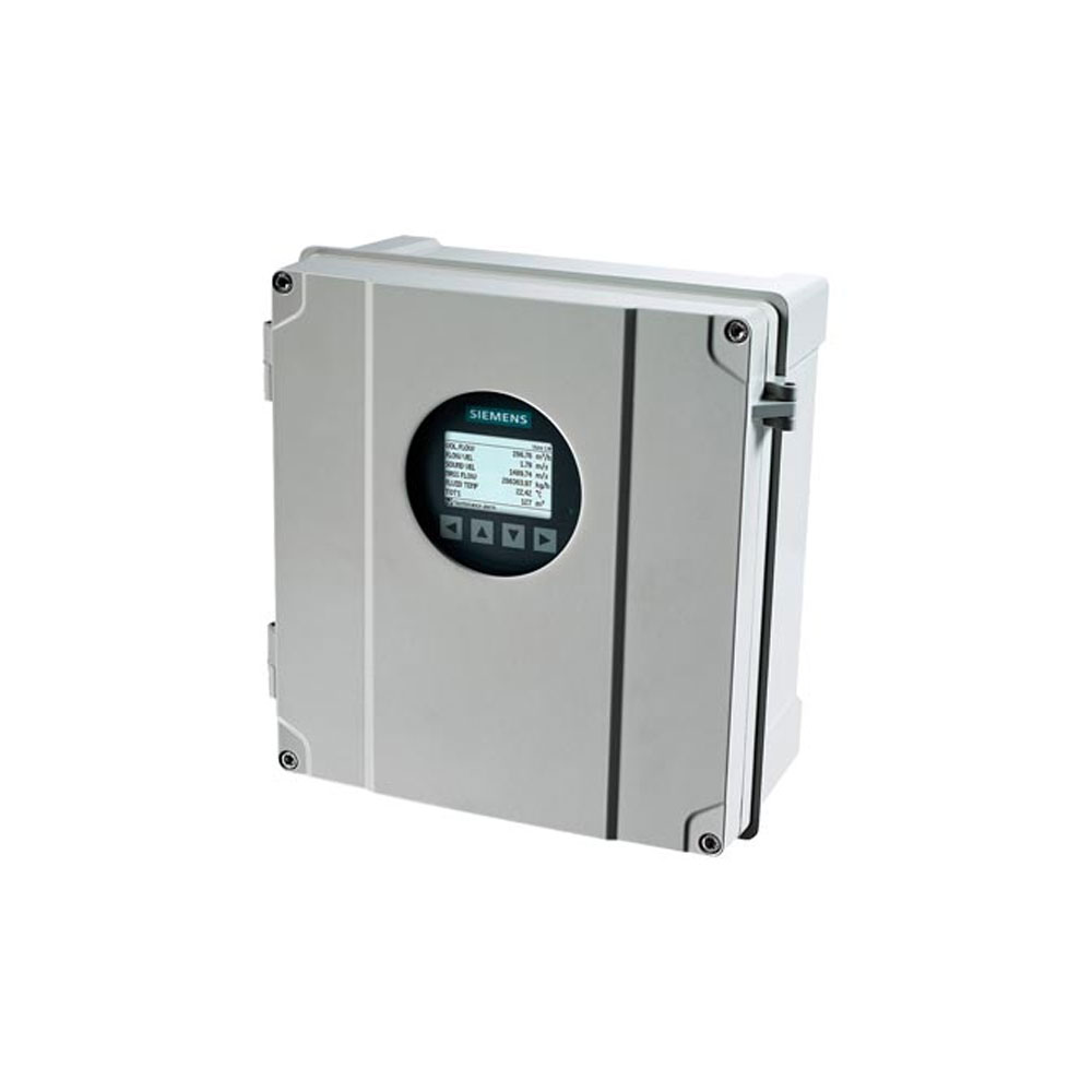
Design
The SITRANS FST030 is designed in an IP67/NEMA 4X aluminum enclosure with corrosion resistant coating. It can be wall or pipe mounted and the enclosure can be locked with a padlock or wired with lead security seals. Includes all flow and DSL functions integrated into one unit.
The FST030 is available as standard with one current, HART 7.5 output and can be ordered with additional input/output functions.
The transmitter has a modular design with discrete, replaceable electronic modules and connection boards to maintain separation between functions and facilitate field service. All modules are fully traceable and their provenance is included in the transmitter setup.
SensorFlash
SensorFlash is a standard, 4 GB micro SD card with the ability to be updated by PC. It is supplied with each transmitter and comes with a complete set of certification documents including report if ordered. Factory conformance certificates are optional at ordering.
The Siemens SensorFlash memory unit offers the following features and benefits:
- Copy site setups to SD card for easy transfer to other similar transmitters
- Permanent database of operational and functional information from the moment that the flowmeter is switched on
- New firmware updates can be downloaded from the Siemens internet portal for Product Support and placed onto Sensor-Flash (unmounted from the transmitter and inserted into a PC’s SD card slot). The firmware is then inserted into the existing flowmeter for system/firmware upgrade.
Function
The following functions are available:
- Up to four configurable outputs and 2 RTD input channels selected at ordering
- Outputs can be individually configured for mass flow, volume flow etc.
- Three built-in totalizers which can count positive, negative or net flows
- Independent low flow cut-offs, adjustable
- Uni/bidirectional flow measurement
- Flow direction adjustable
- Alarm system consisting of alarm-log, alarm pending menu
- Change log, logs all changes made to menu parameters or via communications
- Internal data logger
- Display of operating time with real-time clock
- Flowrate outputs are freely configurable between maximum negative and maximum positive flows according to the sensor capacity
- Limit switches programmable for flow, density and temperature. Limit points can be graded as warning and alarm for values both above and below nominal process conditions
- Zero adjustment menu, with zero point evaluation display
- Full service menu for effective and straight forward application and meter troubleshooting
- Precise temperature measurement ensures optimal accuracy on massflow and density
- Fully compatible with Siemens PDM version 8.2 service pack 1 or higher
Technical specifications
|
Process media |
|
|
Process variables |
|
|
Current output |
|
|
Current |
0 … 20 mA or 4 … 20 mA |
|
Load |
< 500 Ω per channel |
|
Time constant |
0 … 100 s adjustable |
|
Digital output |
|
|
Pulse |
41.6 µs … 5 s pulse duration |
|
Frequency |
0 … 10 kHz, 50 % duty cycle, 120 % overscale provision |
|
Time constant |
0 … 100 s adjustable |
|
Active |
0 … 22 V DC, 30 mA, short-circuit-protected |
|
Passive |
3 … 30 V DC, max. 110 mA |
|
Relay |
|
|
Type |
SPDT dry contact relay |
|
Load |
30 V AC/100 mA |
|
Functions |
Alarm level, alarm number, limit, flow direction |
|
Digital input |
|
|
Voltage |
15 … 30 V DC (2 … 15 mA) |
|
Current |
4 … 20 mA |
|
Functionality |
Reset totalizer 1, 2 and 3, force output, freeze process values, zero point adjustment |
|
Galvanic isolation |
All inputs and outputs are galvanically isolated, isolation voltage 500 V |
|
Alarm and warning limit |
Available for all process values |
|
Totalizer |
Three counters for forward, net and reverse flow |
|
Display |
|
|
SD card functions |
|
|
Ambient temperature |
|
|
Operation |
|
|
-40 … +60 °C (-40 … +140 °F), |
|
-20 … +60 °C (-4 … +140 °F) |
|
Storage |
|
|
-40 … +70 °C (-40 … +158 °F), |
|
Communication |
HART 7.5 |
|
Modbus RTU RS 485 |
|
|
Enclosure |
|
|
Material |
Aluminum |
|
Rating |
IP66/67, NEMA 4X to IEC 529 and DIN 40050 (1 mH2O for 30 min.) |
|
Mechanical load |
18 … 400 Hz random, |
|
Power supply |
|
|
Universal |
20 … 27 V DC |
|
Fluctuation |
No limit |
|
Power consumption |
20 W/22 VA |
|
Minimum pressure for Gas |
7 … 10 bar (100 … 145 psi), typical (gas composition and application dependent; plastic pipes support operation at atmospheric pressure) |
|
Environment Environmental conditions according to IEC/EN/UL 61010‑1 |
|
|
Maintenance |
The flowmeter has a built-in error log/pending menu which should be inspected on a regular basis |
|
Cable glands |
Cable glands are available in nylon, nickel plated brass or stainless steel (316L/W1.4404) |
|
Approvals |
|
|
For non-hazardous area |
No approval required |
|
For hazardous area |
|
|
|
|
Zone 0, 1, 2 |
|
Zone 2 |
|
Zone 0, 1, 2 |
|
|
|
Class 1, Div 1, 2 |
|
Class 1, Div 2 |
|
Class 1, Div 1 |
|
|
|
Class 1, Div 1, 2 (Zone 0, 1, 2) |
|
Class 1, Div 2 (Zone 2) |
|
Class 1, Div 1, 2 (Zone 0, 1, 2) |
|
|
|
Zone 0, 1, 2 (Div 1, 2) |
|
Zone 2 (Div 2) |
|
Class 1, Div 1, 2 (Zone 0, 1, 2) |
|
Certificates |
|
|
CE conformity marking |
|
|
EMC performance |
|
|
Emission |
CISPR 11:2009/A1:2010 and EN 55011:2009/A1:2010 |
|
Immunity |
IEC/EN 61326‑1:2013 |